Module A-118-2V generates the signals white noise, colored noise, continuous random voltage and stepped random voltage.
The noise signal is generated 100% analog by amplification of the noise of a transistor. White and colored noise are usually used as audio sources. The random voltages are normally used as control voltages (e.g. for filter frequency or any other voltage controlled parameter).
The A-118-2V gives you the ability to mix the relative amounts of Red and Blue noise (low/high frequency component) in the colored noise output.
For the continuous random voltage the rate of change (Rate) and amplitude (Level) of the random voltage can be adjusted. The continuous random voltage is used as source for the S&H/T&H unit. The type of operation can be set to S&H (sample and hold) or T&H (track and hold). When T&H is chosen the output signal follows the input signal as long as the Clock input is "high". As soon as the clock signal changes to "low" the last voltage is stored. When S&H is chosen the input signal is sampled at the rising edge of the Clock signal. For the Clock signal a "digital" signal (e.g. Clock, Gate, rectangle output of an LFO) is required. Dual color LEDs are used to indicates the continuous and stepped random voltages.
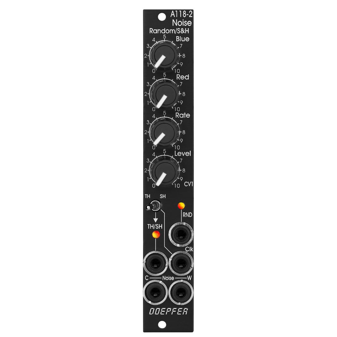
Controls:
- Blue: share of the high frequencies in the the colored noise output
- Red: share of the low frequencies in the the colored noise output
- Rate: rate of change of the continuous random voltage
- Level: amplitude of the continuous random voltage
- TH/SH: switches between T&H und S&H
Inputs and outputs:
- RND: continuous random voltage output (with LED display)
- TH/SH: stepped random voltage output (with LED display)
- Clk: Clock input of the S&H/T&H unit
- C Noise: colored noise output
- W Noise: white noise output
Important notes:
After power on it takes a few minutes until the two noise signals and the random signals are generated. The module is not faulty when after power on the signals do not appear immediately !
The S&H/T&H function is realized by pure analog circuitry (electronic switch followed by a holding capacitor and buffer). Consequently the output voltage drifts a bit in the holding state because the capacitor is discharged by parasitic resistors. The drift depends also upon environmental conditions like humidity or temperature.
The level of the random voltage changes with the settings of the Blue and Red controls. Especially the Red control affects the random voltage level (which is derived by low pass filtering from the colored noise signal) because the Red control changes the share of the low frequencies in the colored noise signal. The effect of the Blue control is much smaller because it changes the share of the high frequencies in the colored noise signal which are filtered out by the low pass of the random circuitry.