Module A-156 is a Dual Control Voltage Quantizer.
A quantizer converts a continous control voltage in the range 0...+10V into a stepped output voltage in the same voltage range (i.e. only certain voltages occur). Normally 1/12 V steps are used to obtain semitone steps. Quantizer 2 of the A-156 allows has more sophisticated quantizing modes like major scale (i.e. only voltages corresponding to the major scale), minor scale, major chord, minor chord, fundamental+fifth and addition of seventh or sixth when chords are selected. Only those voltages appear at the CV output which comply with the selection rule (e.g. minor chord with seventh). The mode setting of quantizer 2 is done with 3 switches (1-0-1 type with middle position). From the factory quantizer 1 is working in the semitone mode. But there is a jumper (J1) on the pc board that can be changed so that even quantizer 1 uses the same scale as quantizer 2. If the jumper J1 is in the lower position (factory setting) the positions of the toggle switches affect only the lower quantizer and the upper quantizer is working in the semitone mode. In the upper position of J1 the positions of the three toggle switches are also valid for the upper quantizer.
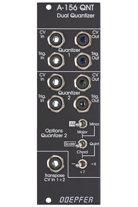
For each quantizer the following in/outputs are available: -
- Control voltage input (CV In): The input for the contiuous voltage to be quantized
- Control voltage output (CV Out): The output of the quantized voltage
- Trigger input (Trig.In): If this jack is left open the quantizer is working permanently. If a rectangle voltage is applied quantisation happens only at the rising edge of the signal (e.g. from an LFO or MIDI-to-Sync interface). Thus the quantizing can be synchronized with other events.
- Trigger output (Trig.Out): Whenever a quantisation happens (i.e. a new voltage is generated at the CV Out) a positive pulse occurs at this output. It may be used to trigger an envelope generator (ADSR) or for triggering other modules (sequential switch A-151, trigger divider/sequencer A-160/161, trigger delay A-162, ...). If none of these functions are used the jack is left open. On top of that the A-156 is provided with a common transpose CV input having an additive effect on both quantizers. This input is quantized in semitone steps. A typical application is the transposition of a sequence generated by the A-155 by a second control voltage (e.g. coming from the MIDI-CV interface A-190).
On top of that the A-156 is provided with a common transpose CV input having an additive effect on both quantizers. This input is quantized in semitone steps. A typical application is the transposition of a sequence generated by the A-155 by a second control voltage (e.g. coming from the MIDI-CV interface A-190). When only the voltage applied to the Transpose input changes no new quantization take place. For a new quantization the voltage applied to the CV In of quantizer 1 or 2 has to change.
Typical applications:
- Quantizing the CV sequence generated by an A-155 (semitone, onyl major scale, only minor scale and so on)
- quantizing the voltage coming from the Trautonium Manual / Ribbon Controller A-198, Theremin A-178 or Light-to-CV module A-179 to get accurate semitones or major/minor scale tones
- arpeggio-like effects with LFO, random, noise, envelope generators as CV sources (for negative or symmetrical voltages an offset must be added, e.g. with the offset/attenuator module A-129-3, to obtain positive voltages for the A-156 input).
For more detailed information please look at the English user's guide : A156_man.pdf. If you want to re-adjust the module you find the adjustment procedure on our website: a156_adjustment.pdf
Technical notes:
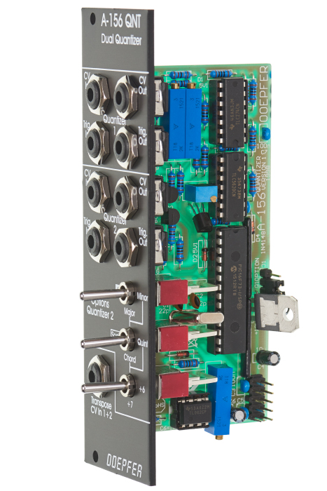
Jumper 1
From the factory quantizer 1 is working in the semitone mode. But there is a jumper (J1) on the pc board that can be changed so that even quantizer 1 uses the same scale as quantizer 2. If the jumper J1 is in the lower position (factory setting) the positions of the toggle switches affect only the lower quantizer and the upper quantizer is working in the semitone mode. In the upper position of J1 the positions of the three toggle switches are also valid for the upper quantizer.
General function and problems of quantizers
When the input CV of the A-156 changes the module converts the incoming voltage into a stepped voltage at the correspondig CV output. For this there the modules uses voltage thresholds in 1/12V steps. If the incoming CV is very close to a threshold value it may happen that this voltage is converted once to voltage 1 and later to voltage 2 (with voltage 2 = voltage 1 +/- one step or +/- 1/12V). The A-156 does not "know" that the voltage comes from the same source. It just converts an incoming non-stepped voltage into a stepped voltage.
Example: think about a sequence with N steps where the voltage of step #3 is close to a threshold. When the sequence is running it may happen that for step #3 two different voltages appear (+/-1 semitone) at different passes. To avoid this flaw the quantizer would have to "know" that it has to convert a sequence with N steps and that after N conversions the same CV as during the last run has to be generated - provided that the voltage is very close to the former value. He would have to memorize the "old" voltages of all N steps and compare them to the "new" voltages. When the difference between an "old" and "new" voltage is below a certain threshold (e.g. less than half a semitone or less than half of 1/12 V, i.e. about 40mV) the old output value is taken. But this job cannot do the A-156 as it does not "know" anything about a sequence structure but simply converts the incoming continuous voltage into a quantized voltage.
To avoid this the quantizer and the sequencer would require a common "supervisor". For example with our Dark Time stand-alone sequencer this would not happen as the quantizers "knows" the values of all controls during the last run because they are stored in an internal memory. When the advance to a new step is triggered the unit compares the new voltage to the stored voltage of the last run. There has to be a significant difference between the two values. Otherwise the same voltage is generated. Without storing the values of the former run this would be not possible. This problem occurs for all quantizers which are not embedded into the sequencer structure because they don't not "know" anything about a sequence but simply convert the incoming non-stepped voltages into stepped voltages.
Even already quantized control voltages should not be used as CV source for the module. In this case similar problems may occur if the voltage steps of the incoming signal are close to the voltage thresholds of the A-156. In this case it may help to add a small offset voltage to the incoming CV signal so that the voltage steps of the incoming signal are no longer close to the voltage thresholds of the A-156. But the general question is: why using a quantizer if the control voltages are already quantized.